PART 2: REGULAR, LONG-TERM MAINTENANCE CHECKLIST
From the June 2019 issue of 48° North.
Last month, we discussed how and why to go through a thorough checklist before starting up your boat’s diesel engine each day. This month, you’ll see that this checklist helps provide some basis for our recommendations for regular longer-term engine maintenance. In case you missed it, that pre-start checklist is as follows:
THE ENGINE START CHECKLIST:
- Key Fluid Levels: engine oil and transmission oil (if applicable), and the coolant level.
- Belt tension.
- The engine seacock is open and the raw water strainer is clear.
- The fuel level and the fuel filter.
- Starting battery voltage.
- The throttle and shifter connections.
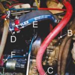
- The engine generally for signs of wear, corrosion and /or leaks (Figures 1, 2).
- Once the engine is running and in gear, recheck the shaft seal.
For the longer term, we start with the list above and assign intervals for more in-depth service as required. Some of these intervals will be determined more by need than timing, such as in the case of corrosion. The proper interval for many things, like engine fluid changes, will depend on use. Whether you decide to base your check on engine-usage-units that are hourly, daily, weekly, or monthly, here are some more items to put on the maintenance checklist:
REGULAR MAINTENANCE CHECKLIST:
- Engine anodes.
- Electrical connections.
- Engine mounts.
- Shaft coupling.
- Water pump impeller.
- Hose clamps.
- And, with flooded batteries, battery water.
Engine anodes (AKA pencil zincs): These need to be checked, and possibly replaced, annually. Check your engine manual for their location, but they are normally located in the raw water part of the cooling system.
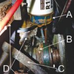
Engine mounts: These should be checked for corrosion as should the rest of the engine (Figure 1C and 3), but also check that the nuts and bolts are tight and sound.
Shaft coupling: Beyond checking it for corrosion and making sure the bolts and nuts are tight, if you suspect the alignment of the engine to the shaft is off due to excessive vibration or other signs of misalignment, you can u-bolt the coupling and use feeler gauges to check the alignment.
Hose clamps: You need to make sure hose clamps don’t loosen up or corrode. It is also a good idea to make sure that they won’t cut you as you are reaching across the engine room. Using the right size and/or encasing the sharp tip with a cover (Figure 1D and 1E) is a good way to do this. For more on hose clamps, refer to our March 2011 48° North article, “Secret Lives of Hose Clamps.”
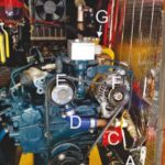
Water pump impeller: Engine water pump impellers should be checked, and probably replaced, at least annually at the start of the season, or sooner with high engine run time. Again, follow your engine manufacturer’s recommendation. To remove the impeller, remove the face plate (Figure 4B), being careful to use the right size and type of tool to remove the screws holding it in place. If the screws are standard fl at heads, it may be best to replace them with screws that have a better tool grip such as hex or Allen head screws.
Once the face plate is off , you can normally carefully pry the impeller out with two fl at standard screwdrivers or needle nose pliers. Try not to damage it as you do; it may still work as an emergency spare. Check your engine manual to see if it has a special recommendation on removing the impeller.
Check the face plate for wear. If it is scored, you may need to replace it, or, fl ip it over if the reverse surface will work against the impeller. Make sure to remove the old pump gasket. To clean and refinish the face plate we use a Scotch-Brite pad. To install the new impeller, lube it with glycerin or Superlube, fold the fins over so it fits into the pump housing and push it back into place. Reinstall the face plate with the new gasket and tighten it into place. If for some reason, you do not have a new gasket, you can cut one out of an old chart in a pinch until you have the proper gasket. If the manual has torque specifications for the water pump face plate screws, use them. If not, carefully tighten down til snug, but don’t strip them. For more information on changing your impeller, refer to our article “Replacing the Impeller on Your Raw Water Pump” from the August 2014 issue of 48° North.
Batteries: If the batteries are flooded, the battery water needs to be kept up. Check every month unless it seems as if there is no appreciable change. Then, go to every two months. If there is still no appreciable change, you could try going to every four months, but no longer. Go back to a shorter interval if you start needing to add a lot of water every time you check them. You can also check the state of each battery cell with a battery hydrometer.
Spare Parts Checklist: Many of the above checks require spare parts to service them if there is a problem. The list of spare parts you should probably carry for your boat is long, goes beyond the engine, and will be particular to the boat. Here are a few thoughts to get you started:
- Full oil change, including oil filters.
- Replacement filters for all the changeable filters on the boat, fuel or otherwise.
- Impellers and gaskets for all pumps. If the boat doesn’t already have a new spare, buy two so the extra will be your spare after you replace the impeller this year. Replace the spare next year when you do your annual service.